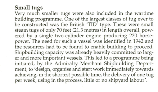
History of TID Class Tugs:
Due to enemy action throughout World War II, many boats and ships were sunk or destroyed by hitting mines, being torpedoed or bombed by aircraft. Major ports and docks were important targets and in London in particular they came under heavy and sustained attack.
As a result and with increasing Naval operations, by 1942 steam tugs were urgently needed for War duties both in the U.K and overseas and the British Admiralty requested the construction of a standard 'Utility' vessel, which could be built quickly and easily using revolutionary construction methods.
Known as 'TID's', 182 of these little prefabricated tugs were built in modular units, by several different yards around the U.K. often by women workers. Brent started off as TID 159 and was the very last of her class to be built being completed in 1946.
In April 1943, a few weeks after the launch of Tid 1 the "Shipbuilding and Shipping Record" published the article reproduced below describing how the tugs were built. The shipyard, referred to and shown in the photographs, was Richard Dunston Ltd of Thorne, Yorkshire. The type is copied at a larger size further down.

Much has been heard from America of the remarkable pre-assembly and prefabrication methods which have been applied to shipbuilding practice in the United States. No country, however, need have any monopoly of any particular kind of shipbuilding technique and although little has been heard of interesting departures from the pre-war conceptions of shipbuilding practice in this country much has been done. That these advances are very real can be gauged from the following general outline of the building of tugs which adopted radical departures from standard practice in shape, details of design and methods of construction.
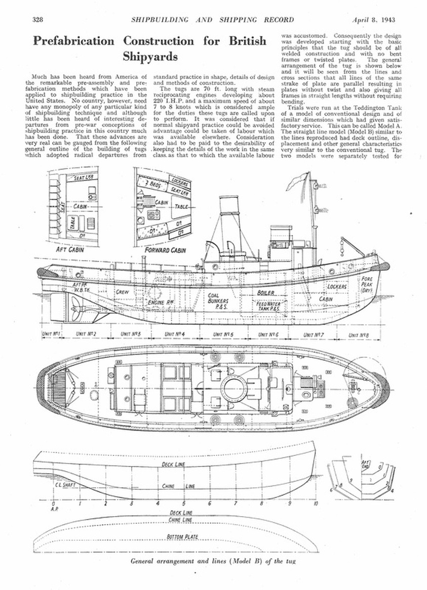
The tugs are 70ft long with steam reciprocating engines developing about 220 I.H.P. and a maximum speed of about 7 to 8 knots which is considered ample for the duties these tugs are called upon to perform. It was considered that if normal shipyard practice could be avoided advantage could be taken of labour which was available elsewhere. Consideration had to be paid to the desirability of keeping the details of the work in the same class as that to which the available labour was accustomed. Consequently the design was developed starting with the basic principles that the tug should be of all welded construction with no bent frames or twisted plates. The general arrangement of the tug is shown below and it will be seen from the lines and cross sections that all the lines of the same strake of plate are parallel resulting in plates without twist and also giving all frames in straight lengths without requiring bending.
Trials were run at the Teddington tank of a model of conventional design and of similar dimensions which had given satisfactory service. This can be called Model A. The straight line model (Modal B) similar to the lines reproduced had deck outline, displacement and general characteristics very similar to the conventional tug. The two models were separately tested for resistance of the hulls by towing at various speeds in their bare conditions without propeller, rudder or sternpost. The propellers and other appendages were then added and the models run under their own power at a series of speeds. Thereafter towing tests with the models tied up to a bollard were carried out and the pulls at various speeds recorded.
Below 7½ knots Model B gave less resistance than Model A, but above that speed Model B became increasingly inferior to Model A. The speed under service conditions with 220 I.H.P. the power of the selected engines was estimated to be of about 8½ knots, so that the rapidly increasing resistance of Model B above 7½ knots did not matter for the requirements of these tugs.
The bollard pull on both tugs is approximately the same.
It was intended to construct the vessels by joining in the shipyard large self contained sections built by constructional engineers. There is an important difference between the standard type of shipbuilding drawing and the drawings to which constructional engineers are accustomed. Moreover, it was particularly necessary constantly to bear in mind that the sections would be made by men having no shipbuilding knowledge. This called for a wealth of detail not considered necessary in a shipyard drawing office. Some impression of this aspect can be gained from the fact that upon to delivery of the first unit over 1,400 prints of drawings had been issued.
It was considered that the maximum amount of work should be done away from the shipyard. At first the work was split up among four contractors, but soon thirteen contractors, each taking one or more 10 ft units were engaged on the work. The tug was subdivided into eight slices cut right across the ship. To avoid confusion of terms each of these pieces was called a unit. The maximum size of each unit was therefore 10 ft long, 17 ft broad and 13 ft deep, the latter being the dimension to the top of the boiler casing. The maximum weight was 6 tons. These dimensions, although too large for rail transport, are actually being transported by lorry, although with the 10 ft length across the lorry the ordinary permissible legal width of vehicle of 7 ft 6 in. is exceeded. Under today’s conditions no objections are raised nor should anyone expect them to be.
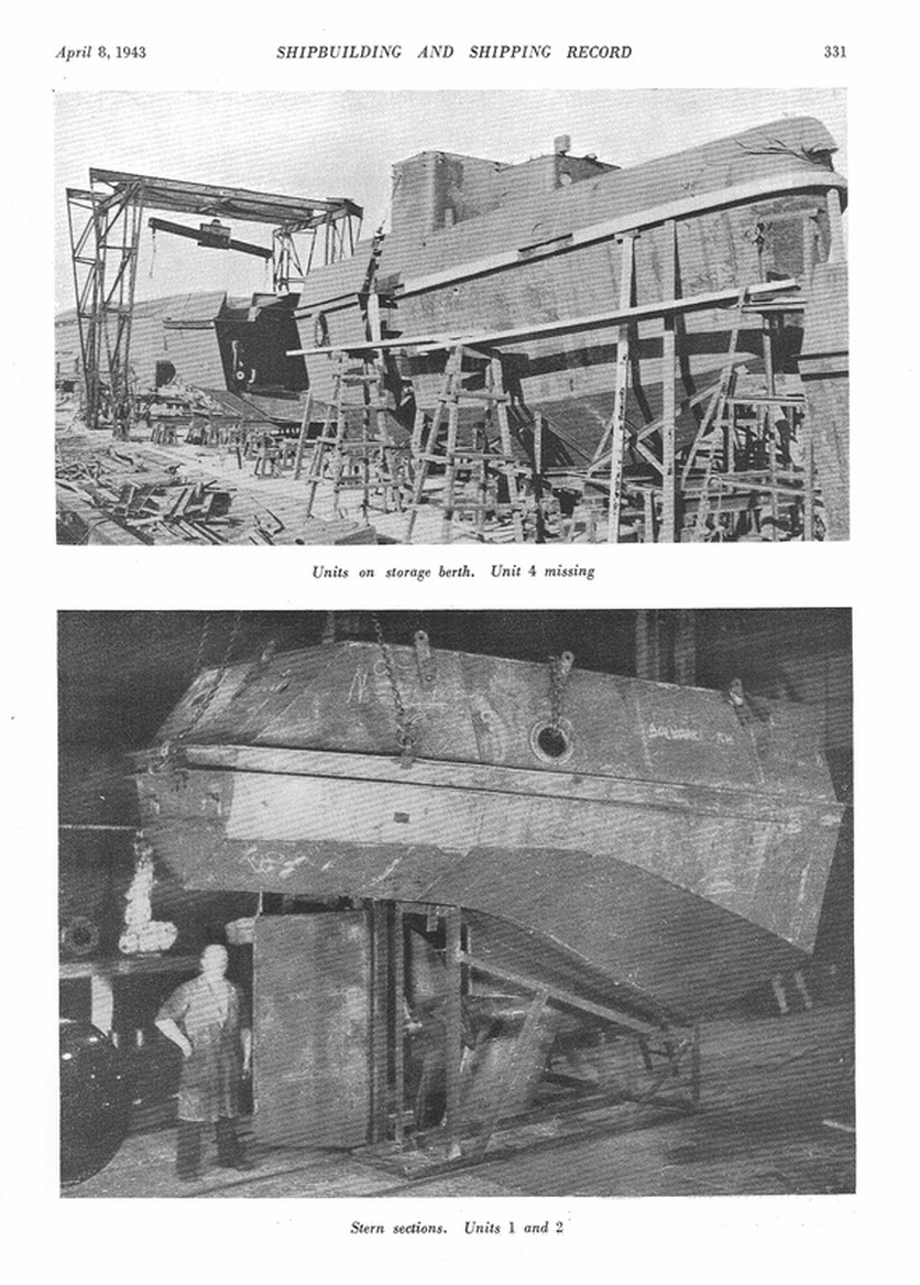
The joints of the units were made by a ring of butt joints round the vessel. No attempt has been made to stagger the joints of different strakes or to strap the butts. All units are constructed in jigs which control the shape and ensure that end faces are square. It will be noted that the joints of Unit No. 2 (aft) were selected to include in this Unit the rudder attachments and stern tube thereby allowing the stern tube to be bored and the tailshaft, propeller and rudder fitted prior to delivery to the shipyard. Fears of alignment difficulties through adopting this rather unorthodox procedure have proved groundless.
Independent drawings were made for each of the eight units of the tug showing details with full dimensions at every frame space, i.e., every 21 in., and also accurate dimensions of the section at both ends of the unit. Each individual plate was detailed separately, dimensions being given between the curved edges of the plates at every frame space of the plate curvature.
Detail dimension drawings were made of all standard ship fittings. Many of these were of the type which had previously been left to the to the yard tom attach to the hull and had hitherto not been sketched in detail. Details of all attachments were also embodied on the steelwork drawings. In spite of the unusually elaborate detailing some of the fabricating contractors found it desirable to make a new set of drawings conforming to their own shop practice and some even went a step further and made detailed drawings on separate sheets of each of the sub-assemblies comprising one unit.
With the shape chosen in which all frame lines in cross section are parallel to one another the basic lines are the plan and elevation of the bottom plate and of the deck plate. With these fixed, the chine line position becomes automatic. These basic lines were therefore laid down on a loft floor and dimensions lifted at every frame. All other required for shape of cross sections and plates were calculated. The curvature of all plates excepting the wrapper plate at the stern and the skeg was such that it was possible to draw the flat plates into correct curvature of the jigs either without any rolling or with a rough preliminary roll.
All main frames were flat bars in straight lengths and were overlapped at the chine and where joining floors in order to get welds of adequate strength. Where plates were curved, the leaf of the frame, when finally assembled, would not be normal to the plate surface and, therefore, when the tangent to the curve of the plate exceeded 1 in 5, i.e. gave more that a 1/16 in. gap at one edge of the frame, the frames were ordered slightly larger and flame bevelled to suit. Where frames or floors crossed longitudinal welds, holes were cut in them for access to the weld. Plates throughout were butted and had no edge preparation excepting on bulkhead plates and on the site weld at the ends of each unit. All joints of units were arranged midway between two frames and the longitudinal seams of plates left unwelded for 10 in. either side of joints in order to permit spring of plates if slight deviation from correct joint dimension were met.
The drawings were issued to prefabricating contractors with a suggested method of jigging which consisted of dividing each main unit into sub-sections so that each plate would have all its stiffeners welded to it and would be curved to the true curvature as obtained from the offsets drawings, a temporary member attached to hold the p[late in this curvature and each set of sections than assembled on end so that the units of the ship were built having transverse cross-sections in a horizontal plane. This description was intended primarily to stimulate contractors in developing their own assembly jigs and freedom of action was left to the contractor to adopt whatever type of jig he considered most suitable this normal practice. There were interesting variations in design.
In the shipyard a reception space was arranged in 80 ft of storage space which was available in line with the proper assembly berth. There were no lifting facilities and consideration of this led to the conclusion that in certain circumstances jib cranes can be unnecessary as well as wasteful of lifting energy and costly in foundation. Consequently the rough gantry shown on page 330 was found quite adequate for hand operation alone and could slide over the reception berth with a 10 ton lifting beam slung from it.
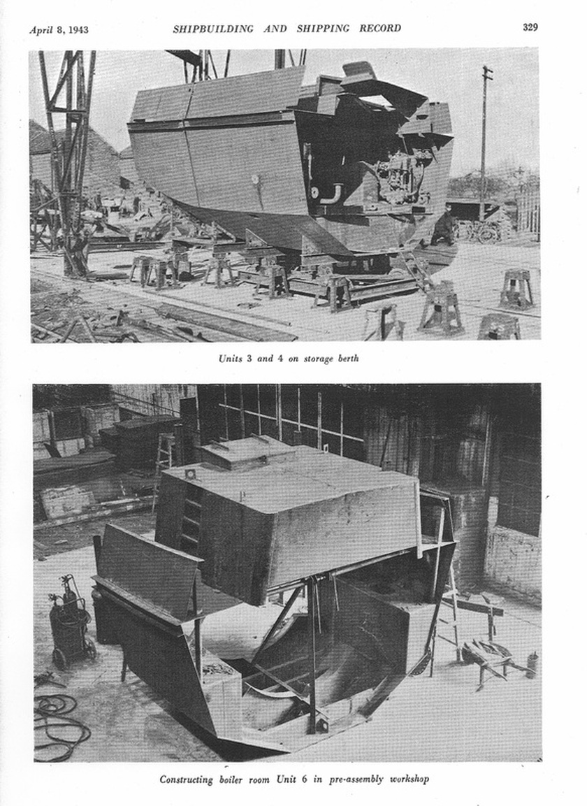
The 12 in. by 12 in. concrete keel blocks on the assembly bocks shown on page 329 and 331 were capped with short lengths of plate and carefully lined up, this lining up remained permanent for all vessels.
Each unit was allotted its correct position on the re caption space, lifted of the lorry by the gantry and dropped on a pair of joists laid across a pair of portable keel blocks at either end of the unit. The joists were fitted with side plates set at the correct width and angle to form a cradle for the unit (Top illustration page 239.) When a complete set of units had been received they were transferred by hand winch and fitted with hydraulic jacks operating wood blocks at the same centres as the cross joists. When these blocks were raised they contacted centring wedges on the cross joists, thereby ensuring that when fully raised the unit would be central on the trolley, and therefore, in true position for lowering on the keel blocks when traversed to the assembly berth. Each unit was transferred in this way and dropped on to the keel blocks with the joints in close contact.
Further positioning of the joints of units was completed by bolts passed through lugs at either side of each unit, the centre line of the bottom plates and the deck which had been popped marked from the template by the prefabricating contactor being checked with centre line of berth.
Since the welding of plates 10 in. either side of joints had not been carried out, any slight deviation of the plates from accurate line at the joint was corrected by wedging from dogs fastened to the inside of the end plates of each unit. To correct slight deviations of the deck it was shored up or drawn down as necessary. The joints were tack welded then finish welded right round the two operators welding in similar positions on either side of the centre line of the ship. Miscellaneous fittings and E.R. valves and pipes were added while the units were in the reception space. The assembly of Unit No. 6 by a sub-contractor is shown on page 329 and the complete stern units Nos. 1 and 2 on page 331.
In practice no measurable distortion has been found after finish welding up. Indeed, in this respect the finished product has been found every bit as good as an ordinary riveted structure. The whole cycle of operations from receiving the units on the assembly berth to launching the ship can easily be carried out in seven days, and a second assembly berth would increase the output to two tugs a week.
The engines and boilers are installed after launching and for this purpose units Nos. 4, 5 and 6 have the upper casings rack welded in place. They are simply removed by cutting after launching and are replaced easily afterwards.
Many of the sections are complete in every respect as far as the detailed fittings are concerned For example, the wheelhouse unit, (No. 6) is fitted out by the pre-fabrication contractors complete with its canvas awning, dodgers and seat for the steersnman and other small details.
In addition to simplifying construction and tapping a source of labour new to shipbuilding technique, the adoption of this principle has effected a saving of steel exceeding 20 per cent.
The tugs are 70ft long with steam reciprocating engines developing about 220 I.H.P. and a maximum speed of about 7 to 8 knots which is considered ample for the duties these tugs are called upon to perform. It was considered that if normal shipyard practice could be avoided advantage could be taken of labour which was available elsewhere. Consideration had to be paid to the desirability of keeping the details of the work in the same class as that to which the available labour was accustomed. Consequently the design was developed starting with the basic principles that the tug should be of all welded construction with no bent frames or twisted plates. The general arrangement of the tug is shown below and it will be seen from the lines and cross sections that all the lines of the same strake of plate are parallel resulting in plates without twist and also giving all frames in straight lengths without requiring bending.
Trials were run at the Teddington tank of a model of conventional design and of similar dimensions which had given satisfactory service. This can be called Model A. The straight line model (Modal B) similar to the lines reproduced had deck outline, displacement and general characteristics very similar to the conventional tug. The two models were separately tested for resistance of the hulls by towing at various speeds in their bare conditions without propeller, rudder or sternpost. The propellers and other appendages were then added and the models run under their own power at a series of speeds. Thereafter towing tests with the models tied up to a bollard were carried out and the pulls at various speeds recorded.
Below 7½ knots Model B gave less resistance than Model A, but above that speed Model B became increasingly inferior to Model A. The speed under service conditions with 220 I.H.P. the power of the selected engines was estimated to be of about 8½ knots, so that the rapidly increasing resistance of Model B above 7½ knots did not matter for the requirements of these tugs.
The bollard pull on both tugs is approximately the same.
It was intended to construct the vessels by joining in the shipyard large self contained sections built by constructional engineers. There is an important difference between the standard type of shipbuilding drawing and the drawings to which constructional engineers are accustomed. Moreover, it was particularly necessary constantly to bear in mind that the sections would be made by men having no shipbuilding knowledge. This called for a wealth of detail not considered necessary in a shipyard drawing office. Some impression of this aspect can be gained from the fact that upon to delivery of the first unit over 1,400 prints of drawings had been issued.
It was considered that the maximum amount of work should be done away from the shipyard. At first the work was split up among four contractors, but soon thirteen contractors, each taking one or more 10 ft units were engaged on the work. The tug was subdivided into eight slices cut right across the ship. To avoid confusion of terms each of these pieces was called a unit. The maximum size of each unit was therefore 10 ft long, 17 ft broad and 13 ft deep, the latter being the dimension to the top of the boiler casing. The maximum weight was 6 tons. These dimensions, although too large for rail transport, are actually being transported by lorry, although with the 10 ft length across the lorry the ordinary permissible legal width of vehicle of 7 ft 6 in. is exceeded. Under today’s conditions no objections are raised nor should anyone expect them to be.
The joints of the units were made by a ring of butt joints round the vessel. No attempt has been made to stagger the joints of different strakes or to strap the butts. All units are constructed in jigs which control the shape and ensure that end faces are square. It will be noted that the joints of Unit No. 2 (aft) were selected to include in this Unit the rudder attachments and stern tube thereby allowing the stern tube to be bored and the tailshaft, propeller and rudder fitted prior to delivery to the shipyard. Fears of alignment difficulties through adopting this rather unorthodox procedure have proved groundless.
Independent drawings were made for each of the eight units of the tug showing details with full dimensions at every frame space, i.e., every 21 in., and also accurate dimensions of the section at both ends of the unit. Each individual plate was detailed separately, dimensions being given between the curved edges of the plates at every frame space of the plate curvature.
Detail dimension drawings were made of all standard ship fittings. Many of these were of the type which had previously been left to the to the yard tom attach to the hull and had hitherto not been sketched in detail. Details of all attachments were also embodied on the steelwork drawings. In spite of the unusually elaborate detailing some of the fabricating contractors found it desirable to make a new set of drawings conforming to their own shop practice and some even went a step further and made detailed drawings on separate sheets of each of the sub-assemblies comprising one unit.
With the shape chosen in which all frame lines in cross section are parallel to one another the basic lines are the plan and elevation of the bottom plate and of the deck plate. With these fixed, the chine line position becomes automatic. These basic lines were therefore laid down on a loft floor and dimensions lifted at every frame. All other required for shape of cross sections and plates were calculated. The curvature of all plates excepting the wrapper plate at the stern and the skeg was such that it was possible to draw the flat plates into correct curvature of the jigs either without any rolling or with a rough preliminary roll.
All main frames were flat bars in straight lengths and were overlapped at the chine and where joining floors in order to get welds of adequate strength. Where plates were curved, the leaf of the frame, when finally assembled, would not be normal to the plate surface and, therefore, when the tangent to the curve of the plate exceeded 1 in 5, i.e. gave more that a 1/16 in. gap at one edge of the frame, the frames were ordered slightly larger and flame bevelled to suit. Where frames or floors crossed longitudinal welds, holes were cut in them for access to the weld. Plates throughout were butted and had no edge preparation excepting on bulkhead plates and on the site weld at the ends of each unit. All joints of units were arranged midway between two frames and the longitudinal seams of plates left unwelded for 10 in. either side of joints in order to permit spring of plates if slight deviation from correct joint dimension were met.
The drawings were issued to prefabricating contractors with a suggested method of jigging which consisted of dividing each main unit into sub-sections so that each plate would have all its stiffeners welded to it and would be curved to the true curvature as obtained from the offsets drawings, a temporary member attached to hold the p[late in this curvature and each set of sections than assembled on end so that the units of the ship were built having transverse cross-sections in a horizontal plane. This description was intended primarily to stimulate contractors in developing their own assembly jigs and freedom of action was left to the contractor to adopt whatever type of jig he considered most suitable this normal practice. There were interesting variations in design.
In the shipyard a reception space was arranged in 80 ft of storage space which was available in line with the proper assembly berth. There were no lifting facilities and consideration of this led to the conclusion that in certain circumstances jib cranes can be unnecessary as well as wasteful of lifting energy and costly in foundation. Consequently the rough gantry shown on page 330 was found quite adequate for hand operation alone and could slide over the reception berth with a 10 ton lifting beam slung from it.
The 12 in. by 12 in. concrete keel blocks on the assembly bocks shown on page 329 and 331 were capped with short lengths of plate and carefully lined up, this lining up remained permanent for all vessels.
Each unit was allotted its correct position on the re caption space, lifted of the lorry by the gantry and dropped on a pair of joists laid across a pair of portable keel blocks at either end of the unit. The joists were fitted with side plates set at the correct width and angle to form a cradle for the unit (Top illustration page 239.) When a complete set of units had been received they were transferred by hand winch and fitted with hydraulic jacks operating wood blocks at the same centres as the cross joists. When these blocks were raised they contacted centring wedges on the cross joists, thereby ensuring that when fully raised the unit would be central on the trolley, and therefore, in true position for lowering on the keel blocks when traversed to the assembly berth. Each unit was transferred in this way and dropped on to the keel blocks with the joints in close contact.
Further positioning of the joints of units was completed by bolts passed through lugs at either side of each unit, the centre line of the bottom plates and the deck which had been popped marked from the template by the prefabricating contactor being checked with centre line of berth.
Since the welding of plates 10 in. either side of joints had not been carried out, any slight deviation of the plates from accurate line at the joint was corrected by wedging from dogs fastened to the inside of the end plates of each unit. To correct slight deviations of the deck it was shored up or drawn down as necessary. The joints were tack welded then finish welded right round the two operators welding in similar positions on either side of the centre line of the ship. Miscellaneous fittings and E.R. valves and pipes were added while the units were in the reception space. The assembly of Unit No. 6 by a sub-contractor is shown on page 329 and the complete stern units Nos. 1 and 2 on page 331.
In practice no measurable distortion has been found after finish welding up. Indeed, in this respect the finished product has been found every bit as good as an ordinary riveted structure. The whole cycle of operations from receiving the units on the assembly berth to launching the ship can easily be carried out in seven days, and a second assembly berth would increase the output to two tugs a week.
The engines and boilers are installed after launching and for this purpose units Nos. 4, 5 and 6 have the upper casings rack welded in place. They are simply removed by cutting after launching and are replaced easily afterwards.
Many of the sections are complete in every respect as far as the detailed fittings are concerned For example, the wheelhouse unit, (No. 6) is fitted out by the pre-fabrication contractors complete with its canvas awning, dodgers and seat for the steersnman and other small details.
In addition to simplifying construction and tapping a source of labour new to shipbuilding technique, the adoption of this principle has effected a saving of steel exceeding 20 per cent.
TID Tugs article and photo from,"Tugs and Towing" by M J Gaston.
Published by Patrick Stephens Limited / Haynes Publishing:
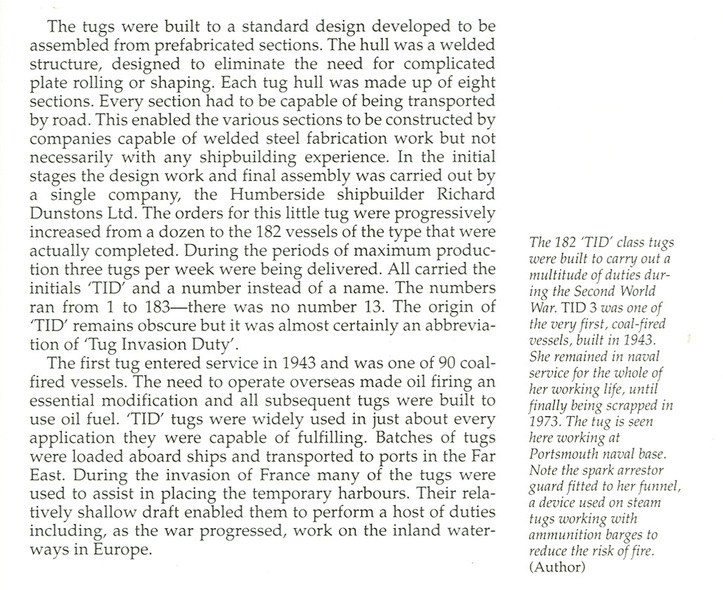
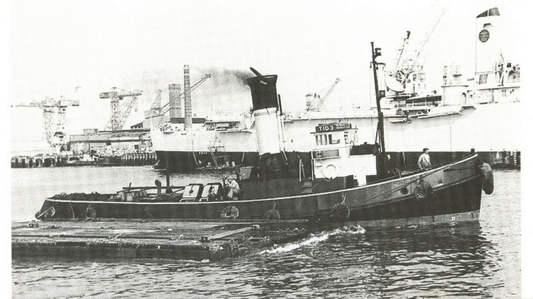
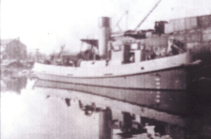
Tid 3 in service
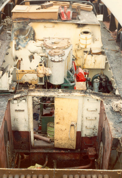
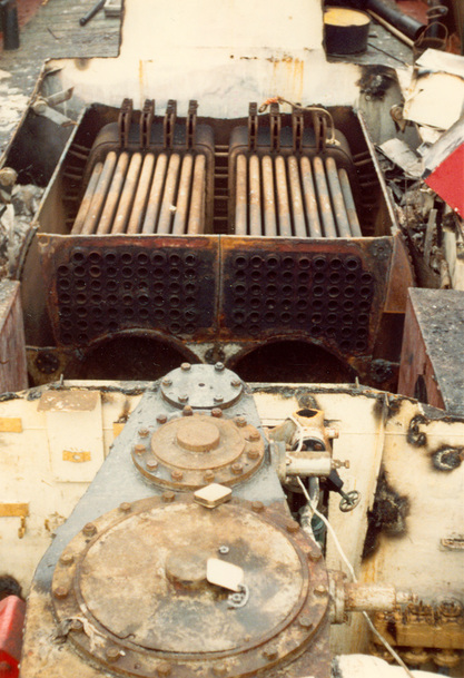
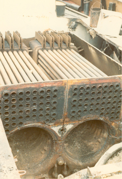
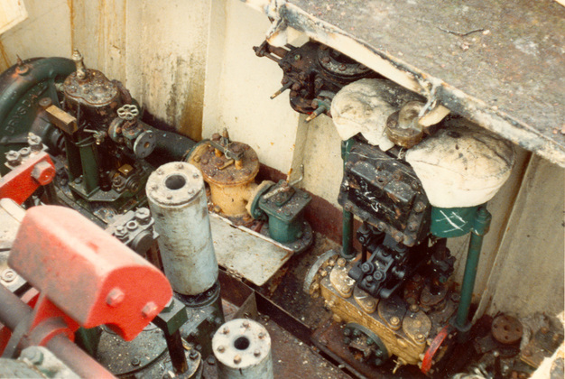
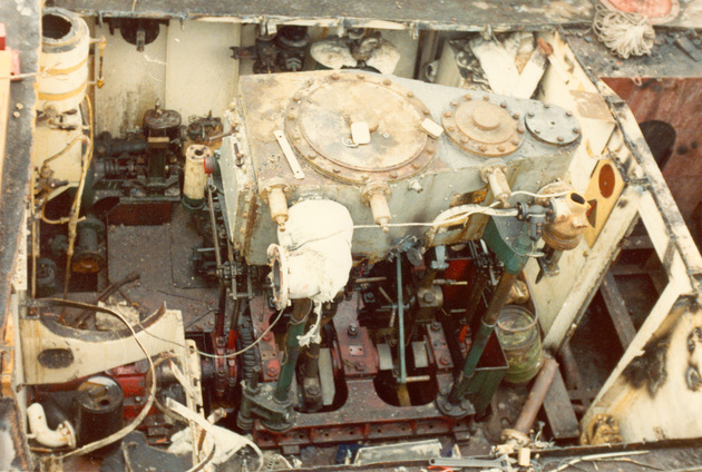
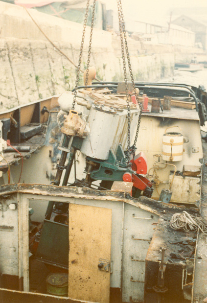
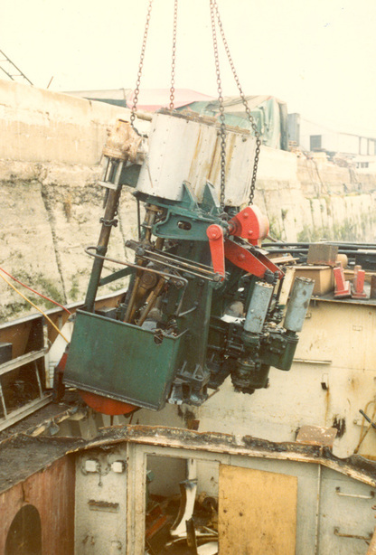
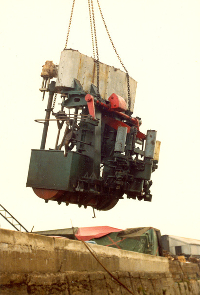
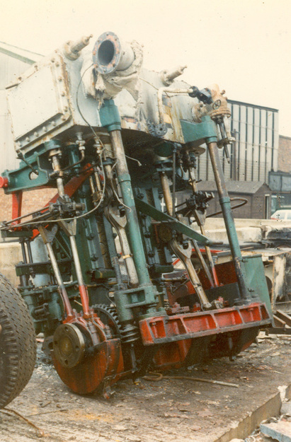
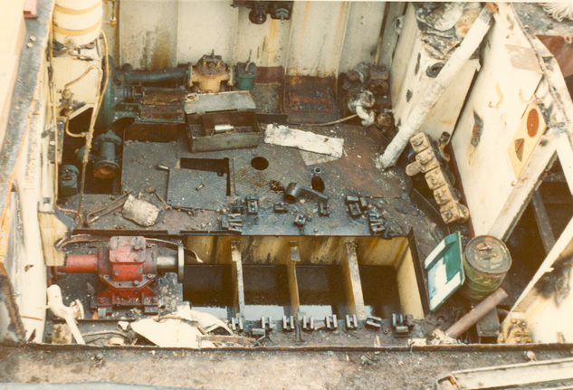
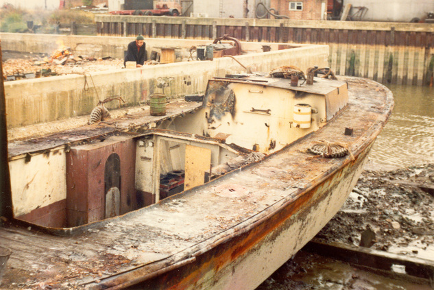
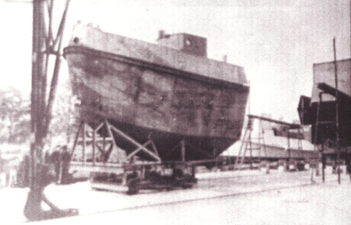
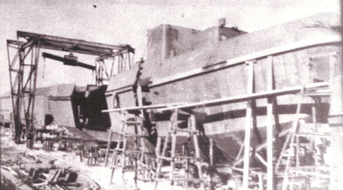
The TID 3 being sadly broken up for scrap in 1973. The pictures illustrate in a unique way how a TID tug is laid out and constructed. Photos from the Ron Hall Collection:
How TID Tugs were constructed. An extract from an article 'Saving a Steam Tug' by Ron Hall written in 1972:
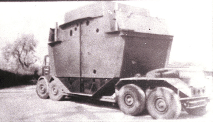
Messrs Dunstan’s design was for an all welded hull that was based on flat surfaces rather than conventional dished plates. The hull was able to be made in sections far inland by ordinary engineering firms and transported to a shipyard for assembly. These sections were eight in number, and to allow for Wartime restrictions on Transportation were of a maximum 10ft long by 17ft wide by 13ft deep and weighed a maximum of 6 Tons.
Much of the welding was done by Government trained women, and as many of the firms concerned were ordinary steel fabrication companies, not familiar with shipbuilding practice, a total of 1400 prints of drawings were issued before the first TID was launched in 1943. Independent drawings were made of each of the eight units, showing details and with full and with full dimensions at every frame space (21ins) and also at each end of the unit which came at a point midway between two frames. Each plate was detailed separately, dimensions being given between the curved edges of the plate at every frame space and also offset dimensions of the plate’s curvature. Detailed dimensional drawings were also made of standard ship fittings. Many of these fittings had not been drawn in detail before but had simply been left to the shipyard to attach.
In spite of the wealth of detail contained in the drawings, many of the fabrication contractors found it desirable to make an entirely new set of drawings to conform to their own shop practice.
Once the units were complete they were transported, sometimes up to 100 miles to Thorne where Messrs. Dunstan assembled the units. Whilst the units were in the reception area, engine room fittings, pipework and auxiliaries were fitted. The units were then taken to the assembly area, positioned in line, and welded together to make a tug complete with canvas dodger and helmsman’s seat. All that had to be added was the main engine and boiler.
Dunston’s tell that the first T.I.D. was towed from Thorne to Hessle, had her boiler towed in and connected up, ran trials back to Thorne, had final adjustments made, and as she went away for delivery towed the next completed hull downstream to receive her engine and boiler. This went on week after week, each completed T.I.D. towing the next. At the peak of their production Messrs Dunston were completing a tug every four and a half days.
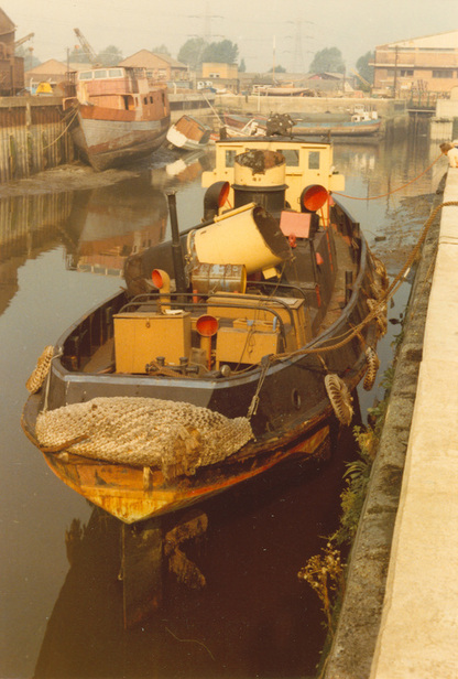
Dunstan's Shipyard at Hessle, showing modular sections. Photographs from the Ron Hall Collection:
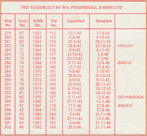
Twenty three TID Tugs including the Brent, were built by William Pickersgill & Sons of Sunderland, who were established in 1838. In 1954 the company merged with Austin & Son, later becoming the A&P Group. The yard finally closed in 1988.
The article reproduced below from their inhouse magazine No.28 published in July 1980, records their Wartime TID Tug construction efforts. The type is copied at a larger size further down:
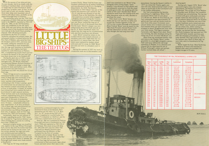
With the success of our shipyard over the past decade, tied in so closely with the building of standard ships one is inclined to forget that we were involved in ‘series production’ in earlier years. In fact, in one hectic spell of only ten months, twenty three sister ships were launched, one of which is still afloat today, probably as the oldest Pickersgill ship in existence.
This particular series was the ‘TID TUG’ programmes of 1944 – 1946 and the surviving vessel is the BRENT, launched as TID 159 (Ship No. 286), on 5th November 1945 and completed on 4th April 1946. With the war over before the ships were finished, most of the Southwick built ships were laid up in the South Dock pending disposal. TID 159 being eventually purchased by the Port of London Authority and given her present name. Her subsequent history is related below by Mr. Ron Hall of Maldon, who saved her from the breakers yard in 1971, and now owns the vessel, sailing her whenever he can.
It is interesting to note incidentally, that the tugs were launched at Southwick in pairs and, after engines had been installed by John Dickinson at Palmers Hill, a completed tug would return up-river to attend the launch of the next pair and tow them down river to be finished off!
During the dark days of 1941 a need arose for small tug units to replace war damaged craft. The British Admiralty commissioned Messrs Richard Dunston of Thorne, Yorkshire to design a steam tug suitable for dock and harbour work. After the hull form was tank tested at Teddington an order was placed for 12 coal fired tugs.
These 12 tugs proved so successful that substantial further orders were placed, some of these tugs were eventually to be used in the ‘D-Day’ operations. Like so many wartime crash programmes culminating in the ‘D-Day Landing’ speed of construction was all important and in this instance it meant discarding old ideas of how to build ships. A simple, all welded, hard chined hull form enabled the hull to be produced in eight separate sections.
These sections were to be manufactured by ordinary engineering firms up to 150 miles apart and transported to Thorne for assembly. At the peak of production Messrs Dunston were producing a hull every 4½ days – a remarkable tribute to their organisation. In all they produced 158 of these tugs, and subcontracted out the building of them. One of these subcontractors was William Pickersgill &Sons who, it appears, built 23 TID Tugs between July 1945 and November 1946.
Incidentally, there were two schools of thought regarding the prefix ‘TID’. Some say it stands for ‘Tug Inshore defence’ and others holding that it stands for nothing more than ‘TIDDLER’!
Dunston’s original design was modified only slightly in the tugs William Pickersgill built, but by this time the boilers had been altered and oil firing was the norm. I am not certain whether the eight hull units were prefabricated and welded by Government trained women welders away from the main building yard, as is the case of the Dunston built vessels or whether the Pickersgill built vessels were made entirely at Southwick.
TID Tugs are 70 ft long overall and powered by a compound engine by John Dickenson & Sons of Sunderland. Main dimensions are H.P. Bore 12” L.P. Bore 26½” by 18” stroke giving 220 I.H.P. Steam is supplied by a scotch boiler 9’ 6” long x 9’ in diameter at 140 P.S.I. and the units have a bollard pull of 2½ tons.
Ship No 286 was completed by William Pickersgill & Sons at Southwick on 12th April 1946 and registered as TID 159 of Sunderland. This vessel along with Ship No 294 (TID 167) and two other TID tugs were purchased from the Ministry of war Transport by the Port of London Authority and re-named ‘Brent’ ex TID 159 ‘Deanbrook’ ex TID 167 ‘Dollar Bay’ ex TID 115 and ‘Lea’ ex TID 168’
The four tugs had wooden tops constructed to their previously open wheel houses and went about their duty in the London Docks. ‘Brent’ had her bows and foredeck reinforced for anchor handling and was allocated to the P.L.A. Dredging department. At H.M. the Queen’s Coronation in 1953 ‘Brent was one of the newest and smartest craft owned by the P.L.A. and she was allowed to tow the firework barge to the festivities. On another less auspicious occasion when engaged in dredging operations along the Victoria Embankment, London a wire snubbed taught and ‘Brent pulled the ring out of the mouth of one of the bronze lions that line the bank! ‘Brent’s’ skipper was very embarrassed about the whole episode as the P.L.A. handbook states very clearly that the rings are for ornamentation only and that mooring is not allowed.
Later ‘Brent’ joined her sisters in the London Docks and worked arduously at mundane tasks until 1969 when she was put into P.L.A. reserve fleet. Her three sisters were replaced by modern diesel units and sold for scrap. In 1970 Brent was sold and went to a breakers yard in Essex.